eShapeoko - Drivers and shield
Problems:
1. Shield does not hold sleep and reset high
2. A/Dual Y not playing right
3. Micro stepping
4. Enable pin with Grbl seems to be inverted (high when it needs to be low)
Solution:
Connected to an arduino everything runs so I knew the driver and motors were good. But I couldn't get things to run with the shield and with Grbl.
1. Rereading the DRV8825 page properly I saw I needed a 10K resistor between the fault pin and the sleep pin to pull it high and activate the board. As the shield connects the sleep to the reset then they are both sorted. I ran the resistor around the edge of the driver so if necessary I can put a heat sink on top.
Edit: The resistor is only needed for the first (mc20a) version of the board, not later ones.
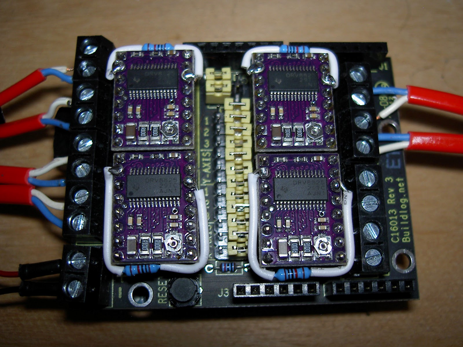

2. The two jumpers need setting above A. This joins the step and drive from the Y and A drivers to pins 3 and 6. The silkscreen and the build log instructions both suggest it's the right-hand pins above DY which need jumping but my meter shows otherwise?

I'll add a link to my .hex file once I have a go with it and see that it won't melt anything.
The arduino sketch below runs the x and y back and forwards which allowed me to check all was well with them.
1. Shield does not hold sleep and reset high
2. A/Dual Y not playing right
3. Micro stepping
4. Enable pin with Grbl seems to be inverted (high when it needs to be low)
Solution:
Connected to an arduino everything runs so I knew the driver and motors were good. But I couldn't get things to run with the shield and with Grbl.
1. Rereading the DRV8825 page properly I saw I needed a 10K resistor between the fault pin and the sleep pin to pull it high and activate the board. As the shield connects the sleep to the reset then they are both sorted. I ran the resistor around the edge of the driver so if necessary I can put a heat sink on top.
Edit: The resistor is only needed for the first (mc20a) version of the board, not later ones.
2. The two jumpers need setting above A. This joins the step and drive from the Y and A drivers to pins 3 and 6. The silkscreen and the build log instructions both suggest it's the right-hand pins above DY which need jumping but my meter shows otherwise?
3. Micro stepping. The DRV8825 can do 1/32 steps but just running through the arduino with this cause me issues so until I need it, all the micro stepping jumpers are off.
4. The enable pin. hmm. The precompiled hex files on the shapeoko forum have some changes to the config.h file (STEPPERS_DISABLE_BIT 0), which is what I need but their step and dir pins are set up for the rev 1 buildlog shield. The rev 3 board has the step/dir pins set up as in grbl but the steppers disable still needs changing. from 1 to 0, the grbl wiki has details on how to compile. For linux go to the directory and:
make cleanmake grbl.hex
The arduino sketch below runs the x and y back and forwards which allowed me to check all was well with them.
#define x_dir 5

#define x_step 2


#define z_dir 7

#define z_step 4


#define y_dir 6

#define y_step 3


//#define enable 8


void setup() {

  pinMode(x_dir, OUTPUT);

  pinMode(x_step, OUTPUT);


  pinMode(z_dir, OUTPUT);

  pinMode(z_step, OUTPUT);


  pinMode(y_dir, OUTPUT);  //low=fwd

  pinMode(y_step, OUTPUT);


  int steps_per_mm = 200; // will be used for positional calibration so that distances can be given in cm in a start table

}


void loop(){


    int x_speed =10; // current range is >5 smaller is faster and weaker

    int x_travel =400;


    int y_speed =10;

    int y_travel =400;


    int z_speed =5;

    int z_travel =200;


      digitalWrite(x_dir, LOW);


  int i = 0;

  while(i<(x_travel))

    {

      digitalWrite(x_step, LOW);

      digitalWrite(x_step, HIGH);

      delay(x_speed);

      i++;

    }


  delay(1000);


  digitalWrite(x_dir, HIGH);


    i = 0;

  while(i<(x_travel))

    {

      digitalWrite(x_step, LOW);

      digitalWrite(x_step, HIGH);

      delay(x_speed);

      i++;

    }


     delay(1000);


//Y test

  digitalWrite(y_dir, LOW);


    i = 0;

  while(i<(y_travel))

    {

      digitalWrite(y_step, LOW);

      digitalWrite(y_step, HIGH);

      delay(y_speed);

      i++;

    }


  delay(1000);


  digitalWrite(y_dir, HIGH);


    i = 0;

  while(i<(y_travel))

    {

      digitalWrite(y_step, LOW);

      digitalWrite(y_step, HIGH);

      delay(y_speed);

      i++;

    }


     delay(1000);


}

Comments
Post a Comment